Recap July's Update & AMA
Navigating the "harsh desert of technical execution" is an unforgiving process. It’s where ambitious ideas are tested against the laws of physics. For our team at Hill Helicopters, that journey has been intense, but the dream is now a collection of proven, functioning, in-house manufactured components.
We’ve reached a new milestone: 50% of the GT50, the first all-new British-built turboshaft engine in 40 years, is now operational on the test bench.
24 Oct 2025
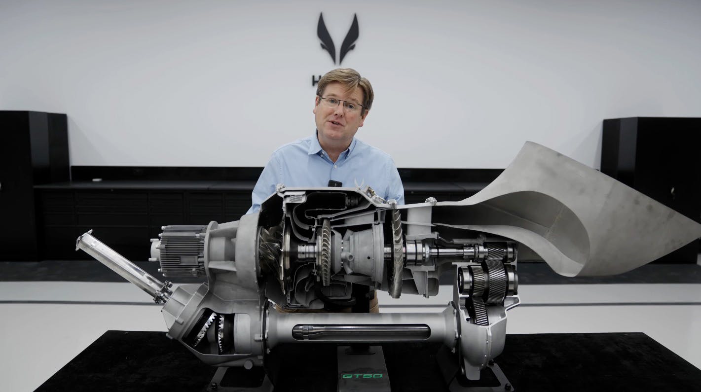
The GT50 Engine: 50% Operational
The GT50 engine comprises four key modules. Today, two of those modules—the Starter Generator and the Engine Drivetrain—are fully operational and undergoing testing.
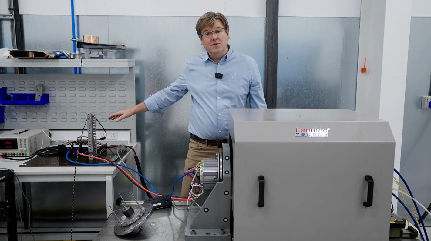
Module 1: The Starter Generator
Central to the aircraft's electrical system, the prototype starter generator has been running throughout its operating speed range. Crucially, it has now demonstrated the ability to generate enough torque to start the GT50 engine.
Achieving this required overcoming significant hurdles in high-speed machine design, precision manufacturing, and robust electronics. One of the biggest challenges was balancing the rotor to a tolerance of less than one micron. The original manufacturing process, which required disassembly after balancing, made this impossible.
We have now developed a new production process and tooling that allows for remagnetisation of the rotor as a complete assembly, solving this critical challenge and ensuring the smooth, vibration-free operation required for a long service life.
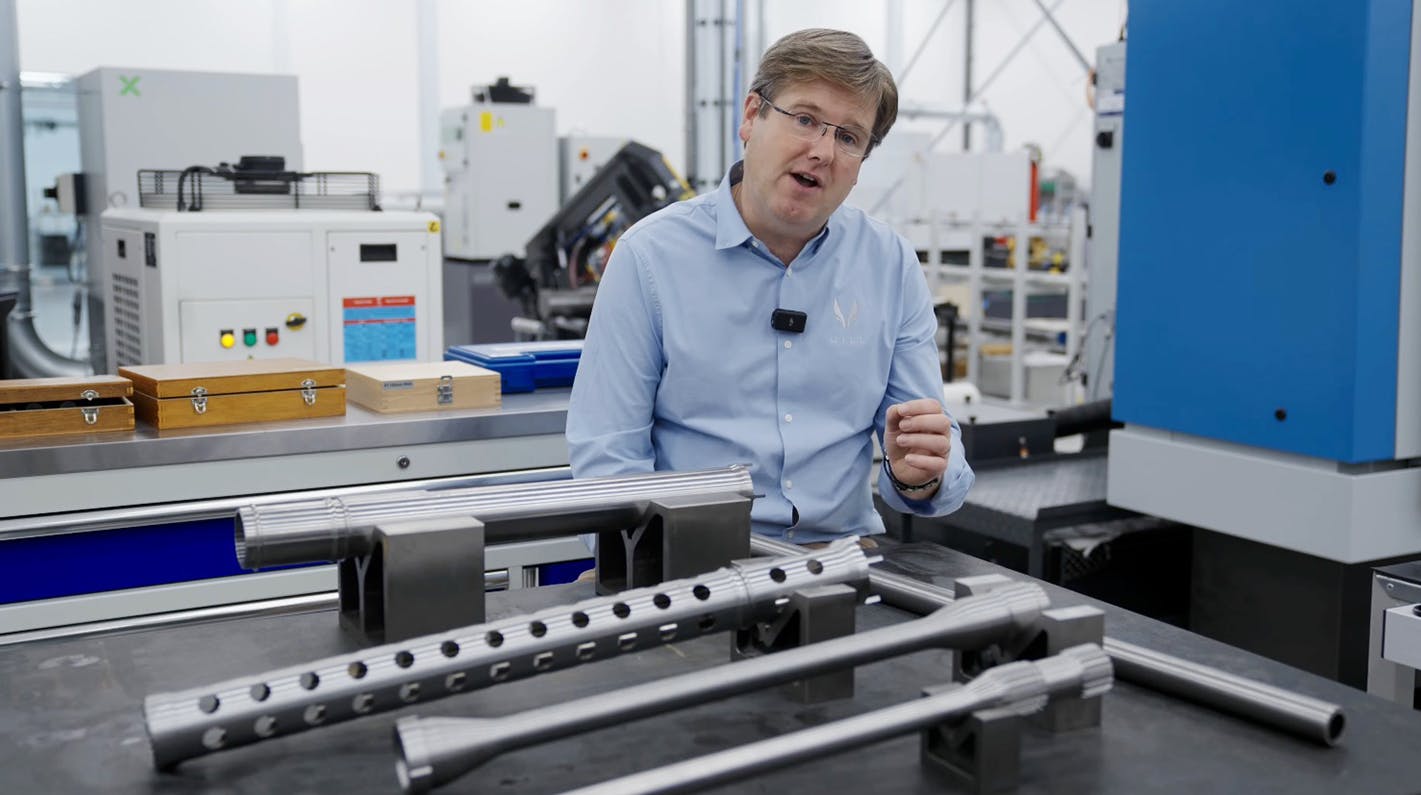
Module 4: The Engine Drivetrain
This module includes the speed reduction gearbox, drive shafts, lubrication system, and engine mounts. Key manufacturing breakthroughs include:
- Thin-Walled Structural Casings: We are successfully manufacturing aerospace-grade aluminum casings with wall thicknesses down to 1.5 mm. This involves advanced casting, precise heat treatments, and controlled machining processes (developed using 3D metal-printed analogues) to manage distortion and hit our critical weight targets.
- Aerospace-Grade Gears: Our painstaking, 30-stage process for producing high-quality aerospace gears is a success. By using "super clean" triple-melted materials, exacting heat treatments, and careful shot-peening, we are creating gears with an infinite fatigue life. The first Hill-manufactured gears are now running on the test bench.
- High-Speed Bearings & Shafts: We are now building conforming, aerospace-grade bearings right here at PC1, achieving our target price point. We have also developed the necessary methods to machine and balance the long, thin-walled, concentric drive shafts, which are notoriously difficult to keep straight after heat treatment.
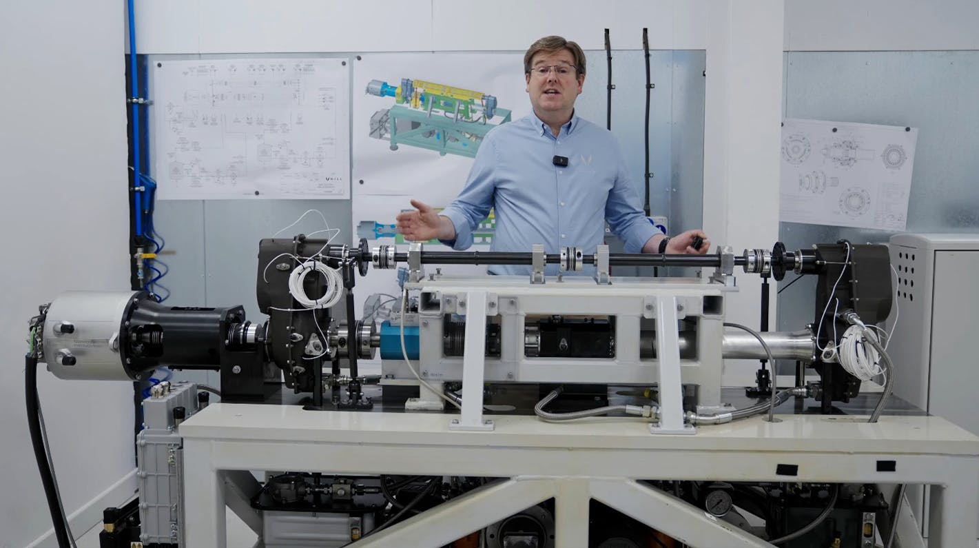
Drivetrain Testing & Validation
To validate this hardware, we developed a specialised, closed-loop test rig that runs two drivetrains antagonistically. This allows us to precisely control torque and speed under demanding conditions while consuming minimal power.
Our "building block" test program is now underway:
- Lubrication System: The first step was validating the lubrication system, visually inspecting all oil jets and calibrating the pumps and heat exchanger.
- Functional Testing: With the lubrication system proven, the full drivetrain was assembled to test all mechanical systems, sensors, and data acquisition.
- Contact Patch Development: We are now assessing the gear contact patches under load, a crucial step for ensuring long-term efficiency and durability.
- Endurance Testing: Once functional testing is complete, we will begin the full engineering endurance tests.
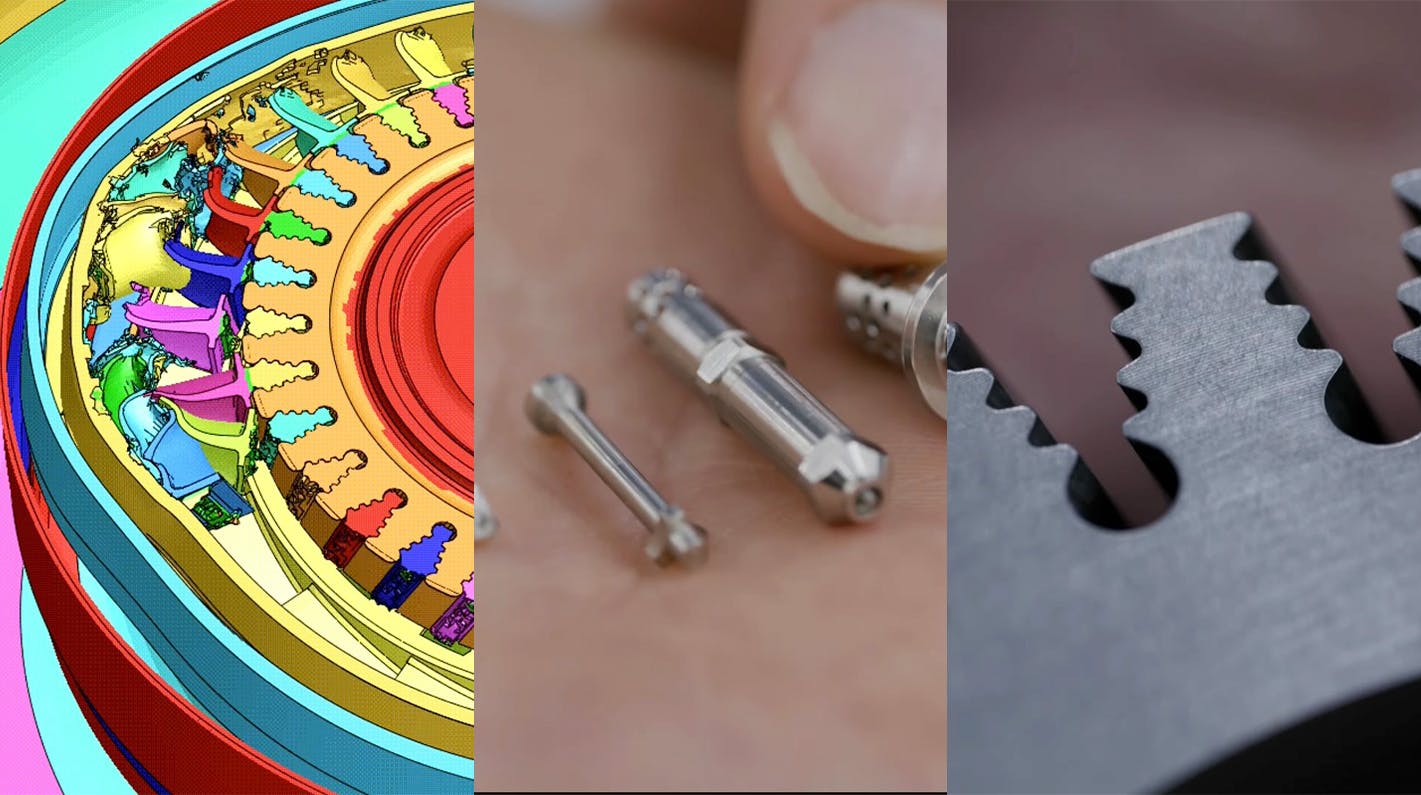
Core Engine Component Manufacturing
Progress is accelerating across all other engine components as we prepare for the first full engine run.
- Turbine Blade Containment: Safety is paramount. Advanced simulations of over-speed burst conditions have validated our gas generator casing design to contain a blade failure.
- Compressor Impeller: The latest high-efficiency titanium impeller is in production. It is now machined from a single heat-treated billet to a finished component in one operation on our new MULTUS machine.
- Fuel Spray Nozzles: To achieve the required 10:1 turndown ratio, we designed a dual-orifice nozzle. This required a full experimental R&D program, including building a specialized test rig with laser visualization to perfect the geometry for mass flow, cone angle, and fuel atomization.
- Nozzle Guide Vane (NGV) & Turbine Blades: Our in-house investment casting process is now producing consistently high-quality, nickel-based superalloy turbine blades. A new higher-temperature furnace is on its way to resolve the final minor "failure to fill" defect in the blades' fine trailing edge.
- Rotor Balancing: To achieve the one-micron balancing tolerance for the final rotor, we have perfected the manufacture of the curvic couplings that lock the rotor components together. These axial gears are critical for ensuring the rotor can be balanced perfectly every time.
The Path to First Engine Run
The next major milestone is the gas generator test. This will be exciting, as the core will expel 2.5 kg/s of air at 800°C near the speed of sound. This requires a highly involved test rig (which will later be extended for the full engine) to safely manage the energy. Testing will proceed in stages: cold cranking, ignition, self-sustaining operation, and finally, full acceleration/deceleration testing.
HX50 Airframe & Components
Progress isn't limited to the engine. Major components for the HX50 airframe are now moving from design into physical production and testing.
Composite Main Rotor Blades
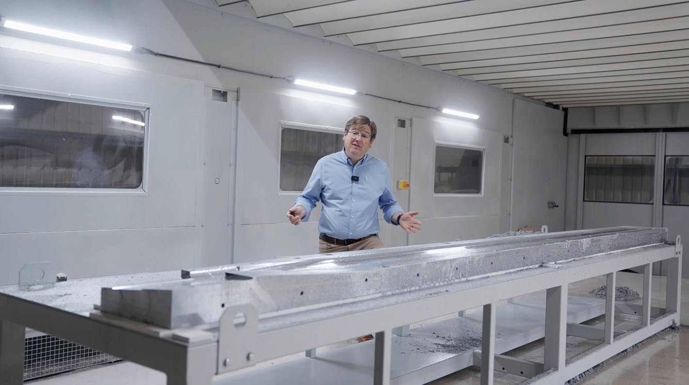
The high-performance, 20,000-hour TBO main rotor blades are now in the tooling phase. We have just completed machining the first prototype HX50 main rotor blade tool.
This complex tool is a "one-shot" compression mould for the out-of-autoclave carbon. It features 15 PLC-controlled electric cartridge heaters for a uniform cure and a spring-loaded relief system to manage thermal expansion.
Undercarriage Systems
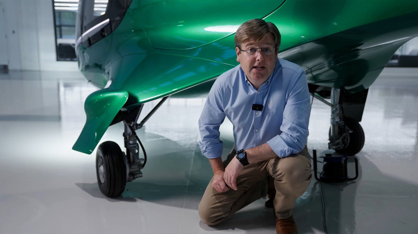
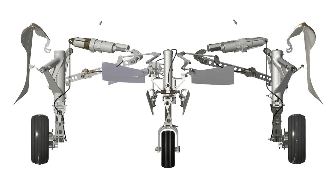
The production-intent undercarriage design is complete.
- Wheeled (Standard): Features robust oleo-pneumatic struts and, significantly, dual-redundant electric actuators. This all-electric design for the gear's actuation eliminates the need for a dedicated hydraulic system for this function, thereby removing potential leak points, simplifying maintenance, and allowing for a 6-second deployment at up to 120 knots.
- Skid (Optional): A simpler, elastoplastic design that offers a 10 kg weight saving.
Test rigs for drop, wheel, and actuation testing are now in development.
Gen 2 Fuselage & Crashworthy Seats
The tail boom assembly will be the first element of the Gen 2 fuselage to be manufactured. It will be built using our new pattern/tooling processes, CNC kit-cutting, and laser ply placement for quality control.
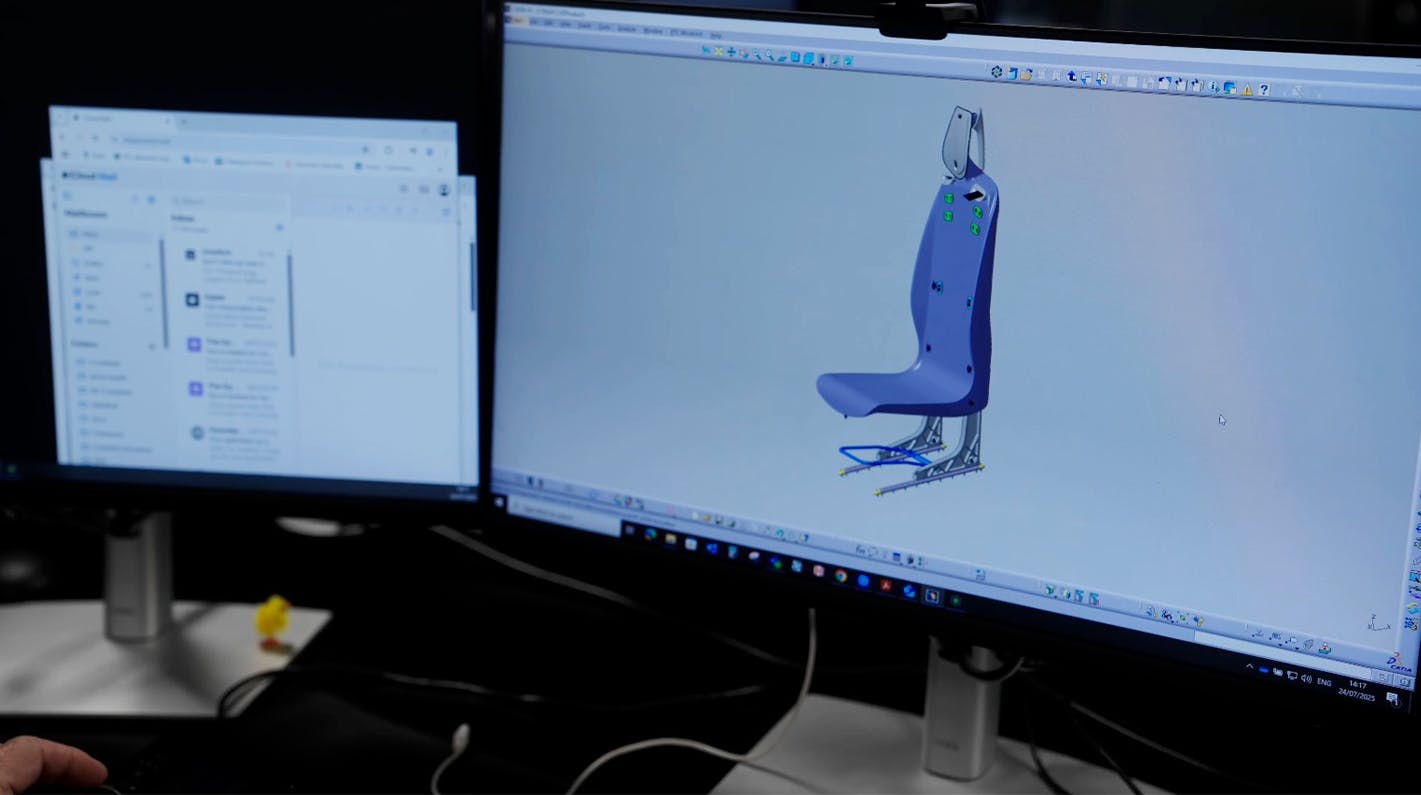
Nearby, the crashworthy crew seat design has been finalised after extensive comfort and trim development. Using advanced digital crash test dummy simulations, we have optimised the structure to reduce spine loads, eliminate occupant "submarining" under the seatbelt, and meet all certification requirements on cost and weight.
Impact-Resistant Windshield
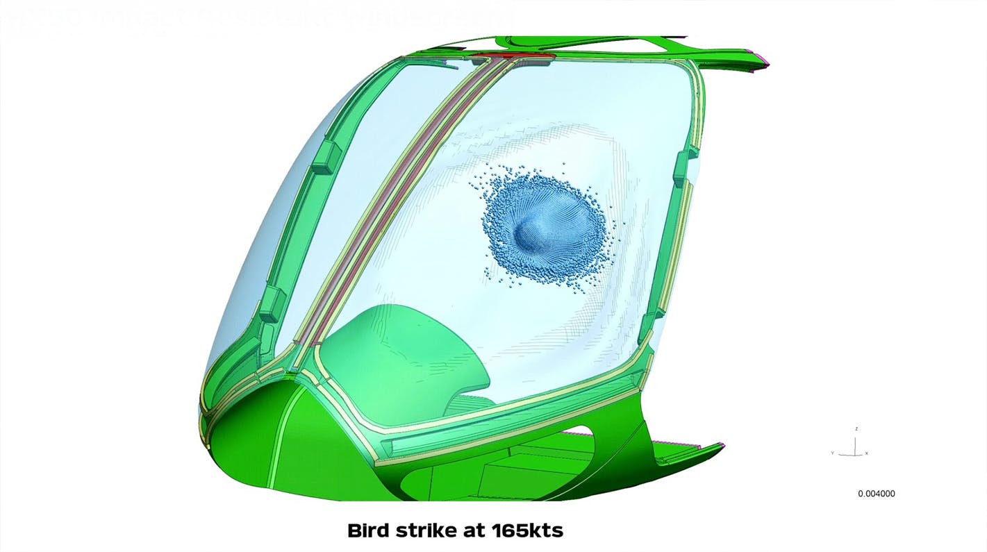
A unique challenge for the HX50's clean aerodynamics is achieving bird-strike resistance without external mechanical fasteners. We are developing a robust bonded joint configuration capable of handling the large deformation of a bird strike. Extensive simulations and material tests indicate this elegant, fastener-free solution will be successful.
Avionics
Electrical System Integration
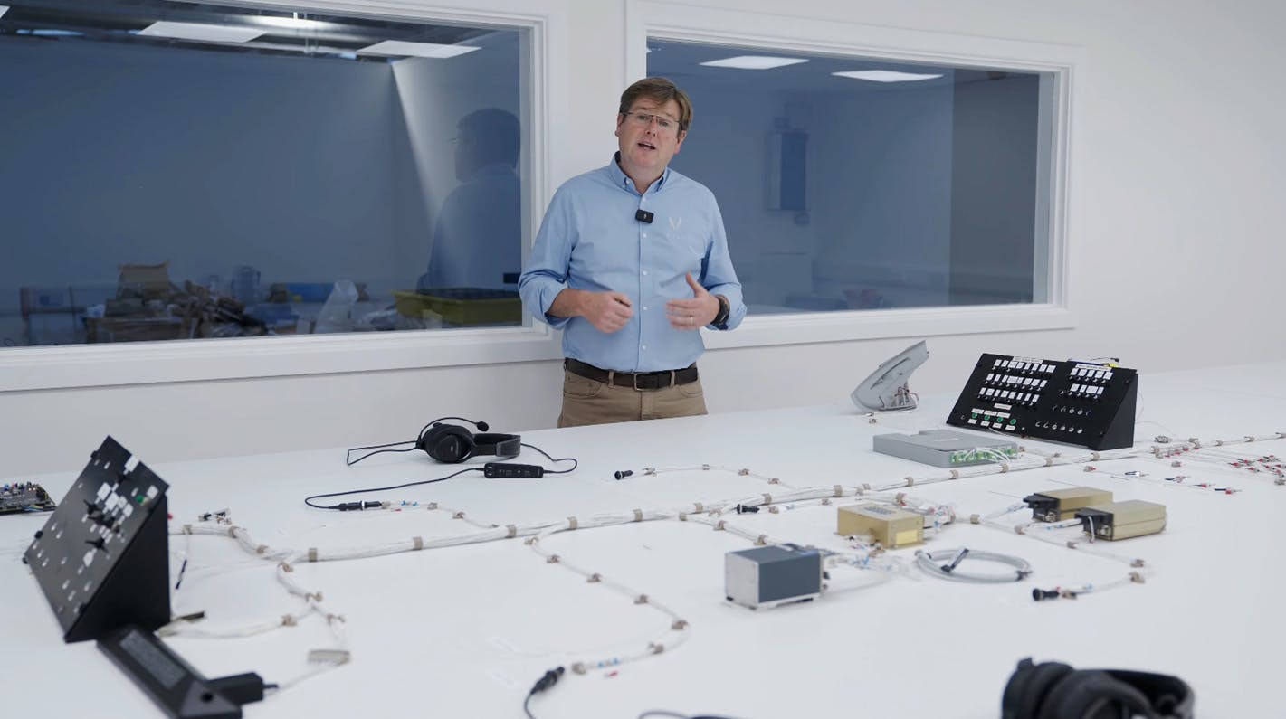
The HX50's electrical system is maturing nicely on our full-scale test bench. The high-voltage system (Starter Generator, Power Management Unit) is operational. Now, our avionics team is integrating the entire low-voltage system—from wiring looms and bulkhead connectors to circuit breakers and buses. This test bench allows us to iron out all system-level issues before they are installed in the prototype aircraft.
The Hill Digital Cockpit (HDC)
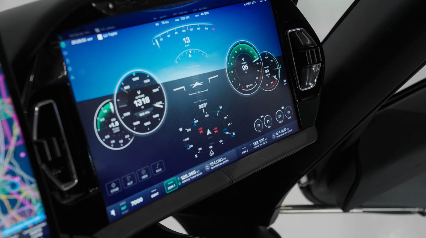
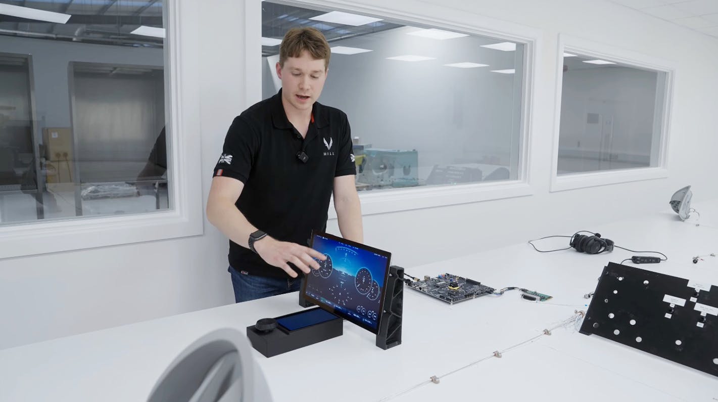
The production-intent Hill Digital Cockpit is now running on its target hardware and is fully integrated with its peripheral systems.
The User Interface
Our primary flight display (PFD) is designed for ultimate clarity and low workload:
- Primary Instruments: A large artificial horizon is flanked by clear, bold airspeed and attitude tapes. The Horizontal Situation Indicator (HSI) integrates a compass, wind bug, and ADS-B traffic display.
- Innovative Altimeter: We've replaced the confusing multi-needle altimeter with a single-needle gauge. The entire clock face represents 1,000 feet, and the digital labels dynamically update as you climb or descend, making it exceptionally easy to read.
- First Limit Power Indicator: This gauge shows your power as a percentage, with dynamic timers that automatically appear when you enter time-limited ranges (e.g., 5-minute takeoff power), ensuring you are always aware of engine limitations.
- Smart Annunciations: In addition to a redundant hardware annunciator panel, the HDC provides immediate, plain-English guidance. If an "Engine Fire" is detected, the POH procedure appears directly on-screen, minimising pilot workload in an emergency.
- Integrated Radio Bar: The touch-screen radio bar allows for easy frequency management and even syncs your "favourites" list from the Hill planning app on your tablet.
Hardware & Redundancy
The system's true innovation lies in its safety architecture. The cockpit runs on two main processors:
- A Primary Display Processor gathers all sensor data (ADAHRS, GPS, engine, etc.)
- A Secondary Display Processor renders the beautiful user interface you see.
The safety-critical feature is that the Primary Processor constantly checks the video output of the Secondary Processor, pixel by pixel. If it detects any error—a crash, a freeze, or misleading information—it instantly intercepts the signal and displays a simple, revisionary PFD to the pilot. This provides an unparalleled level of redundancy.
Controls at Your Fingertips
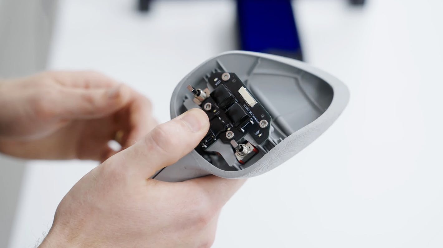
The system is controlled via the cyclic grip, which features an autopilot mode selector, a push-to-talk button, a COM swap button, a landing light switch (with a "strobe" mode for bird deterrence), and a trigger for the force-trim release.
JOIN OUR GROUP PRESENTATION
Are you interested in the HX50? Book your spot in our group presentation and learn why the HX50 will be better than your current helicopter.
What's in the presentation
Who
Mischa Gelb (aka Pilot Yellow) and Ruben Dias
What
Exclusive full details about the HX50 not yet available to the public
How
30 minutes presentation + Q&A
Be part of the journey
Get all the relevant news and updates about the HX50 delivered to your inbox.

HX50
Exterior Concept
Interior Concept
GT50 Turbine Engine
General Aviation 2.0
Hill Digital Cockpit
News & Stories
Technical Details
Range Simulator
Journey to HX50
ADDRESS
Hill Helicopters
Unit 3, Shackleton Way
Stafford, ST16 1GY
United Kingdom
Contact
General Enquiries:
+4401384590700
Accounts:
+4401384590700
Sales:
+4401889228040
hello@hillhelicopters.com
ADDRESS
Hill Helicopters
Unit 3, Shackleton Way
Stafford, ST16 1GY
United Kingdom
© 2025 HILL HELICOPTERS